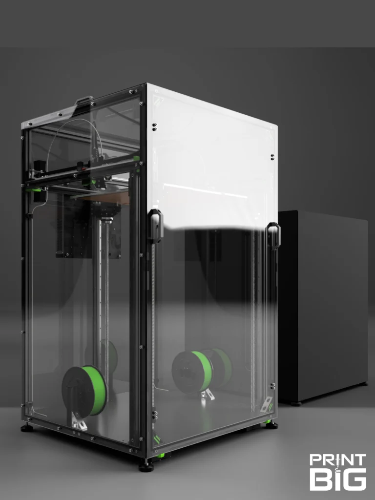
Prusa Maxi
Description |
Dimensions |
Amount |
| NEMA 17 Stepper Motor with Threaded Rod | TR8x4 x 489 mm |
1 |
| 3030 T-Slot Extrusion | 469 mm | 1 |
| Smooth Bearing Rod | 10 x 521 mm | 2 |
| Extrusion Slot Cover | 320 mm | 1 |
| Braided Cable Sleeve | 16 x 250 mm | 1 |
| Braided Cable Sleeve | 5 x 480 mm | 1 |
| Wago Inline Splicing Connector | Wago 221 | 2 |
| Heater Extension Cables | 180 mm | 2 (twisted pair) |
| E-Stepper Extension Cable | 180 mm | 1 |
| E-FanExtension Cable | 180 mm | 1 |
| Print Fan Extension Cable | 180 mm | 1 |
| Filament Sensor Cable | 580 mm | 1 |
| Thermistor Extension Cable | 180 mm | 1 |
| MINDA Extension Cable | 180 mm | 1 |
Please make sure you got everything listed here!
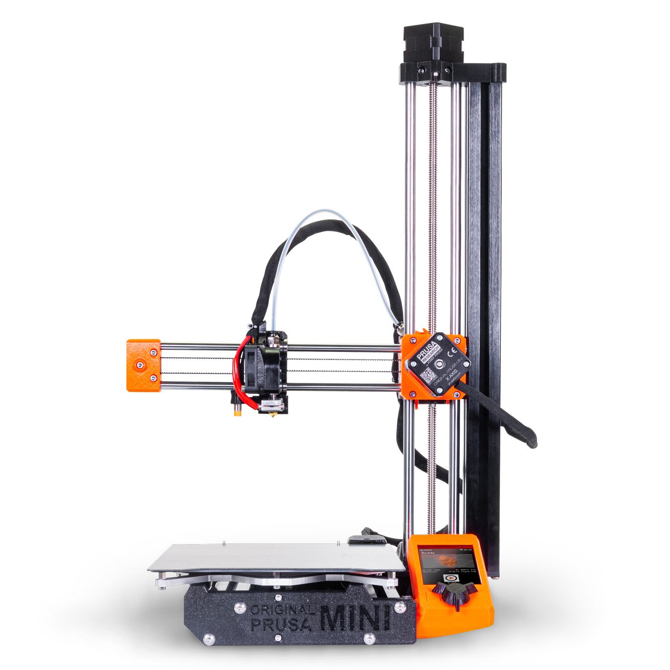
If you are newly building your machine, consult the Original Prusa MINI assembly manual.
Little changes here, except for the lengths of some components of course, and some cable extensions.
We install them exactly like the stock parts. The upgraded parts from this kit come in especially in chapter 2, from steps 42 through 44 and 53 through 62, chapter 3, steps 29 and 30, as well as chapter 5, steps 18 and 19 (as of October 2025).
If your Machine is already assembled, you will have to build back the Frame somewhat, to be able to extend it. This procedure is outlined in this manual.
All photos in this manual are taken from the Original Prusa MINI assembly guide (linked above). Image credits belong to Prusa Research a.s..
Be sure to unplug your printer before opening the electronics cover!
Take care to avoid electrostatic discharges (ESD) as they could damage electronic components.
Chapter 5, steps 19 and 18 (backwards):
Unplug your Printer and open the electronics cover.
Disconnect the following cables from your printers “Buddy Board” (counter-clockwise) and add in the extensions. Do not reconnect them yet:
- Hotend Heater, add the extension cables (twisted pair, red) using the Wago connector
- Hotend Thermistor, two leads: red/black
- Hotend Fan, three leads: black/red/blue
- Print Fan, three leads: black/red/yellow
- Just disconnect the filament sensor, if you have one
- PINDA/MINDA sensor, three leads: brown/blue/black
- Extruder (E-axis) Stepper, four leads: black/green/red/blue
- Just disconnect the Z-stepper

Chapter 3, steps 30 and 29 (backwards):
Unscrew the two M3x20 bolts mounting the trapezoidal nut.

Unscrew the four M3x20 bolts holding the X-axis and take it off of the Z-axis.

Chapter 2, steps 62 – 53 backwards:
Take off the plastic extrusion slot cover and cable, and unscrew the two M3x20 bolts mounting the Z-stepper to the top part, as well as the two M5x16 bolts mounting the top part to the aluminium extrusion.

Carefully take out the top part, stepper and Z-axis bearings. Take the trapezoidal nut off of the old lead screw.

Take out the old bearing rods after loosening the four M3x20 bolts securing it to the MINI-Z-bottom.

Loosen the two M5x20 screws holding the Aluminium Extrusion to the Z plate bottom part from below, and take it out. The inner one is accessible through the MINI-Z-bottom.

Your machine is now upgraded, but you’ll need to edit some settings for the extension to be usable!
You can now rebuild your Prusa MINI with the Upgraded Parts!
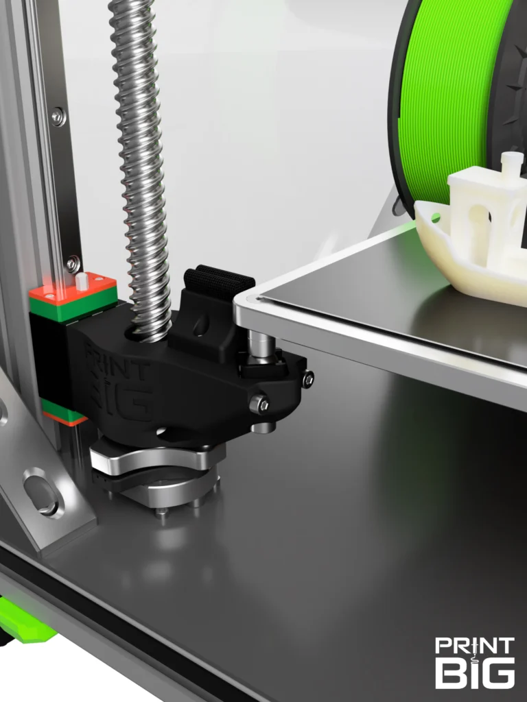
Simply swap the Aluminium Extrusion you just demounted for the extended one, install the extended bearing rods (don`t forget to slide on the bearings!), and install the extended Z-axis stepper (don’t forget to put on the trapezoidal nut!).
Remount the X-axis and plug everything back in with the cable extensions. Swap the filament sensor cable if you have one.
Then, add the new braided cable sleeves and close the electronics cover.
(In short: Follow this manual in reverse or, for more detailed instrctions, the Prusa MINI Assembly manual once again. Approximately from chapter 2, step 42, as of October 2025)

But before you can start printing, we have to adjust some settings on your machine and slicer:
- Plug in and boot up your printer, then go to the settings menu
- Scroll to “Hardware” or “HW Setup” and press the knob for 2-3 seconds to access the “experimental settings”
- Adjust the Z-axis length to 360
- Hit “Save and return” and let the printer reboot
- Lastly, change the maximum print height in your Slicer: With PrusaSlicer, go to “Printers” and set the Max print height to 360 mm

We hope that you are satisfied with your new Prusa MAXI 360 Z-Axis upgrade, and that the installation was a little fun too.
If any questions remain, you have any remarks, or need help with something, don’t hesitate to reach out to us! Write an E-Mail to support@print-big.com to talk directly to our team of engineers and 3D-printing experts.