- 1. Scope of Delivery
- 2. Threaded Inserts
- 2.1. Top Part
- 2.2. Middle Part left
- 2.3. Arms
- 2.4. WobbleX Adaptor
- 3. WobbleX Pins
- 4. POM Bed Bearings
- 5. Wipers
- 6. FK12 Bearing Blocks
- 7. T-Nuts
- 8. Z-Constraint Ball Bearings
- 9. Z-Constraints
- 10. WobbleX Adapters
- 11. Mounting the Arms
- 12. Installing the Ballscrews
- 13. Mounting the Bearing Blocks
- 14. Steppers and Middle Parts
- 15. Belt Drives
- 16. Tensioners
- 17. Lower Parts
- 18. WobbleX Alignment
- 19. Software Changes
- 20. Done!
RatRig V-Core 4 Z-Axis SFU 1605 Upgrade Manual
Description |
Dimensions |
Amount |
| SFU 1605 Ballscrew and Nut | 650 mm |
3 |
| Grease Nipple for ballscrew nut | 3 | |
| FK12 Bearing Block | 3 | |
| Toothed Pulley | 60 teeth | 3 |
| Toothed Pulley | 20 teeth | 3 |
| Timing Belt | 178 mm / 89 teeth | 3 |
| WobbleX WS16 | 3 | |
| Ball Bearing 6800 | 3 | |
| T-Nut | M4 | 6 |
| Threaded Insert | M3 | 36 |
| Threaded Insert | M4 | 12 |
| Threaded Insert | M5 (short) | 12 |
| Cap Head Screw | M3 x 8 | 14 |
| Cap Head Screw | M3 x 22 | 18 |
| Cap Head Screw | M3 x 40 | 12 |
| Cap Head Screw | M4 x 14 | 16 |
| Cap Head Screw | M4 x 20 | 6 |
| Cap Head Screw | M4 x 60 | 2 |
| Hex Bolt | M5 x 30 | 3 |
| Lock Nut | M5 | 3 |
| Washer | M3 | 12 |
| Washer | M5 | 3 |
Description |
Amount |
| Upper Part Left | 1 |
| Upper Part Right | 1 |
| Upper Part Rear | 1 |
| Middle Part Left | 1 |
| Middle Part Right | 1 |
| Middle Part Rear | 1 |
| Lower Part Left | 1 |
| Lower Part Right | 1 |
| Lower Part Rear | 1 |
| Spanner | 3 |
| Arm Left | 1 |
| Arm Right | 1 |
| Arm Rear | 1 |
| WobbleX Adaptor Ring | 3 |
| Wiper | 2 |
| Z-Constraint Left | 1 |
| Z-Constraint Mirrored | 2 |
Please make sure you got everything listed here!
The left/ right/ rear/ 3D-printed parts (on this page) may vary only slightly visually. Compare the images later in this manual closely, and take care to use the right part in every step.
If your upgrade kit was not shipped with threaded inserts already installed in the printed parts, we will start here. If your 3D-printed parts came with the inserts already installed, you can skip ahead to Step 2.
We will need a soldering iron (preferably with a tip specialised for this purpose). Set it to about 300°C. If your soldering iron is not adjustable, just be more careful.
In short, lay the appropriate insert onto its corresponding hole, with the slightly narrower, smooth stud down. Insert the soldering tip and press down only very lightly. The insert will heat up quickly and begin to melt into the hole. Make sure to insert them as straight as possible or the parts won’t fit! Insert the thread only about 90 % with the soldering iron, then press it in all the way against a heat resistant flat surface. Hold it down for a few seconds. This way we ensure the inserts are sitting straight and flush and aren’t pushed back out by the molten plastic.
For more detailed instructions, we refer you to CNC Kitchens short tutorial on best practices when installing threaded inserts into 3D printed parts. Please read/watch the video attentively and follow the recommendations presented.
CNC Kitchen: Tips & Tricks for Heat-Set Inserts
The upper parts take four M3 inserts in the top.
Another four M3 in the bottom.
And four M4 inserts on the bottom inside.
Be especially careful when inserting these. The inner walls of the printed parts are melted easily and there is little material towards the circular cutout.
The middle parts need only two M3 inserts on the side where the steppers will go. Compare the following images and make sure to install the inserts only where shown!
The lateral arms take one M3 insert in the top.
The rear arm takes four M3 inserts like shown, which are only needed for the VAOC module, if you have an IDEX machine.
The WobbleX adaptor rings take two M5 short inserts (the only M5 inserts in this kit). They should be inserted with the pin cutouts facing up, like shown.
Press four steel pins from the WobbleX into the pertinent slots in each adaptor ring and each of the three arms.
The POM bearings for the print bed can also be installed with M6 x 12 bolts now. Be aware of the correct orientation of their slots. Compare the following images of the left, right and rear arms.Make sure to orient the POM parts the right way. Compare with the images here or consult the RatRig guide 02. Z-Axis Assembly, step 14.
Insert the felt pads into the wiper bodies.
The wipers can then be mounted on the lateral arms with M3 x 8 bolts.
Press the FK12 bearing Blocks into the upper parts against a flat surface. Press until it sits flush with the printed part (the interference fit is purposefully tight). Then insert the four M4 x 14 bolts and tighten them down in an X-Pattern. Do this until the Block is fully inserted into the printed part and sitting straight. Be careful not to over-tighten the bolts to avoid damaging the printed part!
When fully inserted into the upper part, the assembly should look like shown, with some clearance under the bearing.
Insert an M4 x 60 bolt into the through-hole of each lateral upper part, and put a T-nut on only lightly.
M4 x 14 bolts are used for the corresponding holes in the middle parts.
The rear upper and middle parts also use M4 x 14 bolts, like shown.
Prepare the Z-constraints with the M6 x 12 bolts and T-nuts from the stock parts.
Press the ball bearings (6800) into the pertinent recesses in the Z-constraints.
Rotate the Z-constraints into place on the linear rails.
Push the (stock) Z-bumpers down against the top of the rails and fasten them very lightly only.
Now butt the Z-constraints against the bumper and tighten them down lightly as well. At this point, we only want them to stop the carriages from sliding off the linear rails.
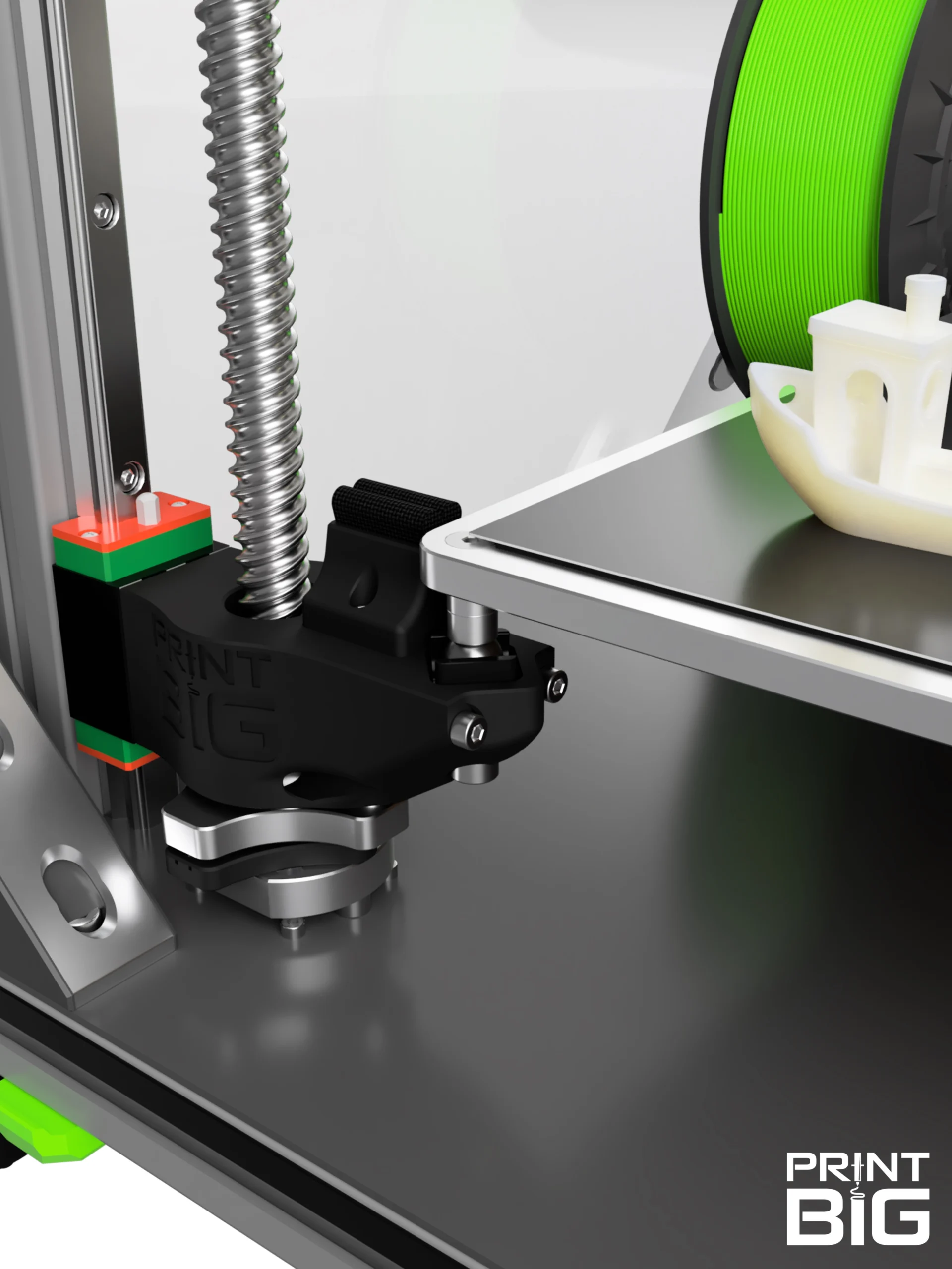
Bolt the printed adaptor rings to the ballscrew nuts with M5 x 16 screws. Use the middle holes like shown. Make sure to orient the rings the right way by having the exposed pins face away from the flange of the ballscrew nut (compare image)!
You can also mount the grease nipple to the ballscrew nut while you’re at it.
Butt the WobbleX aluminium rings against the adaptors. Though you could do it now, we think it’s easier to install the ball bearings in step 17.
Mount the new arms to the linear carriages using two M4 x 100 and two M4 x 20 bolts each, like shown.
Afterwards, lay your Printer on its side carefully. We recommend laying it to the right for better accessibility to an M4 bolt in step 12.
Screw out your machines feet about 20 mm.
Insert the ballscrew through the base plate. Be careful not to drop the WobbleX or adaptor ring!
Push it up through the arm and insert the short end into the 6800 ball bearing in the Z-constraint.
Push the upper part and bearing block onto the ballscrew, and make sure they are pressed right up against the printers base plate. Re-loosen the Z-constraint and bumper from step 8 if necessary. Rotate the T-nut into the front extrusion of the frame.
Don’t tighten the T-nut yet.
Clamp the ballscrew to the bearing block with the square nut and don’t forget to tighten its grub screw.
Hold the assembly in place while you screw in four M3 x 8 bolts from the other side.
You can now tighten the T-nut from the previous sub-step (don’t overstrain the printed part!). Tighten the Z-constraint and bumper from step 8 as well.
Put a stepper motor into the middle part, its connector facing to the back of the machine.
Hold this assembly onto the upper part and lightly mount it to the front frame extrusion using the T-nut. It should just hold itself in place for now.
Put the belt around both toothed pulleys and mount them on the stepper shaft and ballscrew together. The mounting side of the large pulley is facing the ballscrew, while the small pulley must be the other way around (compare images). Don’t fasten them yet.
Leave the smallest possible gap between the small pulley and the stepper motor. Orient one grub screw of the pulley to the flat of the stepper shaft and tighten both screws on this pulley.
Make sure that the stepper motor is sitting in the middle part straightly and align the large pulley with the small one. The belt must run straight and shouldn’t rub anywhere. Turn the small pulley a few times to confirm, then tighten the large ones two grub screws as well.
Put the tensioner assemblies together from the lower parts and spanners, as shown, using the M5 x 30 bolts, washers and nuts. Just put the nut on the end of the bolt, don’t tighten it.
It might be necessary to loosen the T-nut from step 13 (marked with the yellow arrow here) almost entirely to get the four M3 x 40 and two M3 x 22 bolts aligned correctly through the lower part. Fasten it evenly in a zig-zag pattern, analogous to the procedure in step 5.
Finally tighten the bolt from step 13 but don’t overstrain the printed part.
Put four M3 x 22 bolts through the lower part and spanner and screw them into the stepper motor, so that the washers barely touch the lower part. We will tighten them once the belt is tensioned.
Dial in the belt tension (shown in yellow for visibility) using a wrench or pliers on the M5 nut (yellow circle). Test the tension with your finger or an Allen key.
Then tighten the four Stepper mount screws from the last sub-step, to lock it in place.
You’re done on this side! Go back to step 11, and repeat the steps for the right and rear side drives.
If you need to however, don’t forget to loosen the four stepper mount screws before, and re-tighten them after.
After finishing the installation of all three ballscrews, it is time to right the machine up again. Finally install four ball bearings into each WobbleX assembly: Lift the arm up, and put a steel ball between each set of pins. They should snap to the magnets behind the steel pins in the aluminium ring.
Push the Arm back down and make sure it is sitting correctly on the ball bearings with its pins. (The balls are shown as a pill shape here, to represent their range of motion)
But before you can start printing, we have to adjust some settings in the config file of your machine.
In the RatRig online interface, navigate to Machine ➔ /config, find the printer.cfg file (not RatOS.cfg) and open it.
The ball screws have a lead of five millimetres and are now belt driven with a mechanical advantage of 3:1, which means we have to set the “rotation_distance” value to 1.666666667 (mm/rev).
Enter this value exactly for all three motors: [stepper_z], [stepper_z1] and [stepper_z2].
Through the compact WobbleX-system and some clever construction, you have also gained around 5 mm of build volume. Set the new “position_max” to 505 (mm).
If any questions remain, you have any remarks, or need help with something, don’t hesitate to reach out to us! Write an E-Mail to support@print-big.com to talk directly to our team of engineers and 3D-printing experts.


